
+86-400-808-1508 zhaoxuemei1@huxishiye.com
Language
Please Choose Your Language

Views: 0 Author: Site Editor Publish Time: 2026-08-07 Origin: Site


Forcing immiscible liquids like oil and water into a stable, uniform mixture without rapid phase separation is a fundamental engineering challenge. Inconsistent droplet size distribution leads to product instability, shortened shelf life, phase separation, and batch rejection, costing manufacturers significant time and material resources. Achieving long-term emulsion stability requires precise mechanical energy application to overcome the natural tendency of liquids to separate.
The High Shear Homogenizer serves as the industry standard for controlling droplet size. Understanding its internal mechanics is a prerequisite for accurate equipment specification, process design, and reliable scale-up from benchtop to production. Without a firm grasp of how mechanical and hydraulic forces interact within the mixing head, engineers risk specifying inadequate equipment that fails to deliver the required particle size reduction.
Stable emulsions depend on achieving a narrow, sub-micron droplet size distribution, driven primarily by the intense hydraulic and mechanical shear generated within a rotor-stator workhead.
Selecting between batch and inline homogenizer configurations dictates not only process efficiency but also the thermal management, throughput capability, and scalability of the emulsion.
Successful scale-up from a laboratory homogenizer to a production-scale inline homogenizer requires matching the tip speed and shear rate rather than simply scaling by volume.
The geometry of the stator (slotted, square-hole, or fine-screen) must be carefully aligned with the specific formulation rheology to optimize droplet breakdown.
Over-processing, cavitation-induced wear, and excessive heat generation are the primary implementation risks, requiring precise control of residence times and cooling systems.
The core architecture of any high-performance mixing system relies on the precision engineering of a high-speed rotor rotating within a stationary stator. This design features a tight radial clearance, typically ranging from 0.15 to 2.0 mm. This microscopic gap is where the majority of the work occurs, transforming raw motor power into targeted fluid disruption. The tighter the tolerance, the higher the shear rate, provided the motor can handle the increased resistance.
The operation follows a distinct three-stage process dynamic that ensures continuous fluid turnover:
Stage 1 (Suction): High-velocity rotation of the rotor blades creates a powerful vacuum, drawing liquids and solids from the center of the vessel or feed line directly into the workhead. This axial draw is critical for incorporating floating powders or heavy liquids that might otherwise settle.
Stage 2 (Centrifugal Acceleration): Centrifugal force drives materials toward the periphery of the workhead, subjecting them to intense mechanical milling in the rotor-stator gap. The fluid velocity increases exponentially as it moves outward from the center of rotation.
Stage 3 (Hydraulic Shear): Materials are expelled at high velocity (up to 40 m/s) through the stator openings, experiencing extreme hydraulic shear and rapid pressure drops. This sudden change in velocity and pressure tears the droplets apart.
This high-velocity circulation ensures flow path integrity. It guarantees that 100% of the product passes through the high-shear zone, effectively eliminating localized bypass and dead zones within the mixing vessel. A well-designed rotor stator homogenizer will turn over the entire batch volume multiple times per minute, ensuring uniform energy distribution.
Mechanical shear involves the physical tearing and compression of droplets within the microscopic gap between the rotor tip and the stator inner wall. This physical interaction is responsible for the initial breakdown of the dispersed phase. The rotor blades act like microscopic hammers, physically smashing larger droplets against the stationary inner wall of the stator before they are forced through the openings.
Hydraulic shear relates to the fluid velocity gradients, turbulence, and high-frequency acoustic energy created as liquid is forced through the stator perforations. This secondary shear mechanism further reduces droplet size and ensures uniform distribution. As the fluid exits the stator, it hits the slower-moving bulk fluid in the vessel, creating massive turbulence and eddy currents that continue to break down the dispersed phase.
Rapid pressure drops inside the workhead induce cavitation—the formation and violent collapse of micro-bubbles. This phenomenon generates localized shockwaves that further disrupt droplet interfaces, enhancing the overall emulsification process. While cavitation is beneficial for droplet breakdown, excessive cavitation can lead to pitting and premature wear on the stainless steel components of the workhead.
The geometry of the stator significantly influences the performance of the equipment. Different head designs are tailored for specific applications, and selecting the wrong geometry will result in inefficient processing or complete failure to emulsify.
Stator Type | Primary Application | Flow Rate Impact | Typical Droplet Size |
|---|---|---|---|
Slotted Disintegrating | General emulsification, solid breakdown | High flow, excellent pumping | 5 to 10 microns |
Square-Hole Emulsifying | Liquid-liquid emulsions, creams | Medium flow, high shear | 1 to 3 microns |
Fine Screen | Ultra-fine emulsions, difficult polymers | Low flow, maximum shear | Sub-micron |
Slotted disintegrating heads are the workhorses of the industry, best for general-purpose emulsification, high-flow rates, and breaking down solid agglomerates. Square-hole emulsifying heads are designed specifically for liquid-liquid emulsions, providing high-frequency shear to reduce droplet sizes to the sub-micron range. Fine screen stators are ideal for ultra-fine emulsions and dispersion of difficult polymers, sacrificing overall flow rate for maximum localized shear.
The success criteria for stable emulsions involve achieving sub-micron droplet sizes, typically 1 to 3 microns for standard high-shear units, alongside a tight, monodisperse distribution curve. A narrow distribution prevents Ostwald ripening and coalescence, where larger droplets absorb smaller ones over time, eventually leading to visible phase separation.
The interplay between chemistry and physics is vital. Surfactant and emulsifier adsorption kinetics must align with the homogenizer's residence time. Emulsifiers must coat and stabilize newly formed droplets before they can collide and coalesce back into larger drops. If the mechanical shear creates surface area faster than the chemical emulsifiers can cover it, the droplets will simply recombine as soon as they exit the workhead.
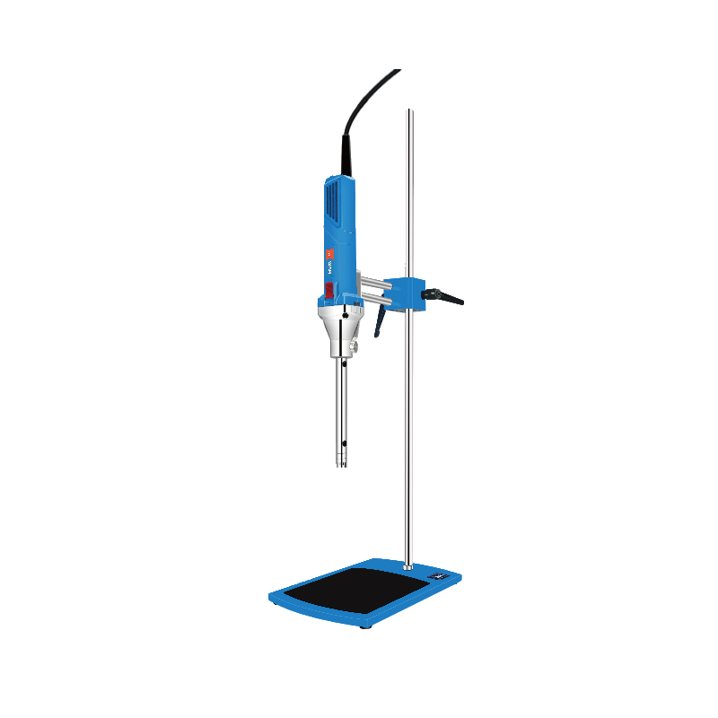
A laboratory homogenizer plays a crucial role in R&D execution. It is essential for proof-of-concept testing, determining minimum shear requirements, and processing small batch sizes ranging from 0.5L to 10L. Formulators rely on these benchtop units to establish the baseline parameters for new products, testing different emulsifier ratios and processing times.
However, scale-down units present specific limitations. Challenges include wall effects in small glass beakers, localized heat spikes, and the risk of false-positive stability results due to unrepresentative flow dynamics compared to production-scale vessels. A beaker on a lab bench does not replicate the hydrostatic pressure or the complex flow patterns of a 5,000-liter stainless steel reactor.
Batch homogenizers are immersed directly into mixing vessels. They are ideal for processing moderate volumes, variable batch sizes, and formulations requiring concurrent bulk agitation to maintain suspension. They are highly flexible but can suffer from localized mixing if the vessel geometry is poor or if the fluid viscosity is too high for the unit to turn over the entire batch.
An inline homogenizer is installed in a recirculating loop or single-pass continuous pipeline outside the vessel. The advantages include self-pumping capability, a 100% product pass guarantee, elimination of bypass, and superior thermal management via inline jacketed piping. Inline systems facilitate continuous, automated manufacturing setups with precise flow control, ensuring every drop of product receives the exact same amount of shear energy.
Feature | Batch Homogenizer | Inline Homogenizer |
|---|---|---|
Installation | Top-entry or bottom-entry in vessel | External piping loop |
Bypass Risk | Moderate to High (depends on agitation) | Zero (100% pass guarantee) |
Thermal Control | Relies on vessel jacket | Can use inline heat exchangers |
Scalability | Limited by vessel size and flow patterns | Highly scalable, continuous flow |
Advanced multi-stage configurations, such as dual-rotor or three-stage rotor-stator sets, are evaluated for applications requiring rapid processing of highly stable nano-emulsions. These setups often achieve results without requiring high-pressure valve homogenizers, simplifying the process line and reducing maintenance overhead.
There is a performance trade-off to consider. Increased mechanical shear stages lead to increased flow resistance and backpressure, which correspondingly raises the motor horsepower requirements for the system. A three-stage inline unit will require a significantly larger motor to achieve the same throughput as a single-stage unit, and it will generate substantially more heat.
Tip speed, measured in meters per second (m/s), is the critical metric for comparing machine performance across different scales, rather than raw RPM or horsepower. It defines the maximum velocity at the rotor's edge and is the primary driver of hydraulic shear.
The calculation for Tip Speed is: Tip Speed (v) = π × D × N, where D is rotor diameter and N is rotational speed in revolutions per second. For example, a small lab unit spinning at 10,000 RPM might have the same tip speed as a massive production unit spinning at 1,500 RPM, provided the rotor diameters are scaled correctly.
Shear rate is defined as the velocity gradient across the rotor-stator gap: Shear Rate = Tip Speed / Rotor-Stator Gap Width. Using this value ensures consistent energy input across different machine sizes during scale-up. Maintaining a constant shear rate is the fundamental rule of moving a process from the lab to the production floor.
Fluid viscosity directly impacts pumping efficiency and shear delivery within the workhead. High-viscosity fluids resist flow, requiring more energy to draw into the stator. If the fluid is too thick, the rotor will simply spin in a localized cavity, failing to draw in new material.
Many emulsions exhibit shear-thinning (pseudoplastic) behavior. They become less viscous under the intense shear of the workhead, which can temporarily improve flow rates during processing. Understanding this rheological shift is critical for sizing the motor and the transfer pumps.
When viscosity thresholds exceed 5,000 to 10,000 cP, a high shear homogenizer loses self-pumping efficiency. At this point, auxiliary positive displacement pumps or scraped-surface vessel agitators are required to feed the workhead and prevent the system from starving.
Wetted parts must be selected based on chemical aggressiveness and abrasiveness. Common materials include 316L stainless steel, Hastelloy, Titanium, or Stellite-coated wear components for enhanced durability when processing abrasive slurries or highly acidic formulations.
Shaft sealing technology is critical to prevent product leakage and contamination. Options include single mechanical seals for basic applications, double mechanical seals with pressurized liquid barriers for sterile or abrasive applications, and lip seals for simpler, low-pressure setups.
Sanitary standards are essential for pharmaceutical, biotech, cosmetic, and food manufacturing. Equipment must feature CIP/SIP (Clean-In-Place / Sterilize-In-Place) capability and comply with FDA, EHEDG, and 3-A sanitary standards to ensure no product residue remains trapped in the workhead between batches.
A common mistake is assuming linear volumetric scaling. Scaling up a 1-liter laboratory process to a 1,000-liter production vessel by simply multiplying motor power by 1,000 often results in catastrophic failure. The fluid dynamics change completely at larger volumes.
The mitigation framework requires strict engineering rules:
Maintain constant tip speed across all machine sizes.
Match stator shear-gap geometry exactly.
Calculate equivalent energy dissipation rates (W/kg).
Adjust residence times to prevent over-processing.
Ensure the bulk agitation in the production vessel matches the turnover rate of the lab beaker.
High mechanical energy input translates directly into heat generation through viscous dissipation. This thermal dynamic can severely impact sensitive formulations, causing proteins to denature or polymers to degrade.
Mitigation strategies are necessary for temperature-sensitive active pharmaceutical ingredients (APIs), vitamins, or volatile fragrances. These include double-jacketed process vessels, inline heat exchangers installed immediately after the workhead, and cooling jackets on the inline homogenizer housing itself.
Applying excessive mechanical shear presents a significant risk. It can deplete surfactant molecules from newly created droplet interfaces faster than they can readsorb, leading to immediate droplet coalescence. More shear is not always better; there is an optimal processing window for every formulation.
Over-processing can also trigger an unintended phase inversion, such as flipping an oil-in-water emulsion to a water-in-oil emulsion, completely destroying the product structure and rendering the batch unusable.
Process optimization involves utilizing Variable Frequency Drives (VFDs) to fine-tune rotor speed, monitoring real-time viscosity changes via inline sensors, and establishing strict cycle time limits to prevent degradation.
To ensure successful emulsification and reliable scale-up, implement the following steps:
Define your target droplet size distribution and document the formulation's viscosity profile under varying shear rates before selecting equipment.
Conduct pilot trials using scalable inline units to validate tip speed and shear rate calculations against real-world fluid dynamics.
Specify stator geometry based on the hardest-to-disperse phase of your formulation, prioritizing shear over flow rate if sub-micron droplets are required.
Integrate inline heat exchangers or jacketed piping if processing temperature-sensitive materials to counteract viscous dissipation.
A: A high shear homogenizer uses mechanical and hydraulic shear via a rotating rotor-stator head (speeds up to 40 m/s), making it ideal for standard emulsions down to ~1 micron. A high pressure homogenizer forces fluid through fixed micro-channels at extreme pressures (up to 30,000+ psi) to achieve sub-micron nano-emulsions.
A: Yes. When equipped with a slotted disintegrating head, the powerful suction draws in and breaks down solid agglomerates, dispersing them uniformly into the liquid phase without clogging.
A: Utilize jacketed mixing vessels, install inline heat exchangers immediately downstream of the workhead, or select an inline homogenizer with a cooling jacket to manage viscous dissipation.
A: Separation often results from insufficient shear time, mismatched stator geometry, or a lack of adequate emulsifiers to stabilize the newly formed droplets before they collide and coalesce.
A: Tip speed is the critical metric. It determines the actual shear velocity at the rotor edge, ensuring consistent energy input across different machine sizes, whereas RPM varies drastically with rotor diameter.
A: Switch to an inline system when you need a 100% product pass guarantee, are scaling up to volumes where batch turnover is inefficient, or require continuous, automated processing with precise thermal control.


