
+86-182-1720-1300 zhaoxuemei1@huxishiye.com
Language
Please Choose Your Language

Views: 0 Author: Site Editor Publish Time: 2026-08-16 Origin: Site


Under-speccing laboratory mixing equipment creates severe operational risks. Ruined batches, stalled motors, and shattered glass reactors often result from inadequate torque. As fluid viscosity changes during chemical reactions or formulation processes, maintaining consistent agitation requires dynamic torque compensation. You cannot rely merely on high rotational speed. Selecting the correct mixing apparatus means moving beyond basic volume capacities. You must critically evaluate a holistic matrix of torque ratings, motor feedback mechanisms, and impeller geometries. Failing to account for fluid resistance leads to equipment failure and compromised experimental data. When a polymer resin thickens mid-reaction, a weak motor will drop its RPM, altering the shear rate and ruining the yield. We will break down the physical mechanics of stirring torque and provide a technical framework for specifying the right equipment for your lab.
Torque represents the rotational force required to overcome fluid resistance. We measure this force in Newton-centimeters (N·cm). In laboratory mixing, the relationship between rotational speed (RPM), viscosity, and torque demand is highly non-linear. It follows an exponential curve. When you increase the speed of an impeller in a viscous sample, the torque load increases far beyond a simple 1:1 ratio.
In fluid dynamics, the power required to drive an impeller scales with the cube of the rotational speed. The torque scales with the square of the speed. Doubling your RPM demands four times the torque. Attempting to force high RPMs in viscous materials without sufficient torque causes immediate mechanical distress. The motor will draw excessive electrical current trying to maintain the set speed. This results in motor stalling, severe overheating, or permanent mechanical damage to your laboratory mixer.
Newtonian fluids present predictable torque requirements. Their viscosity remains constant regardless of the shear rate applied by the impeller. Water, light oils, and simple solvents fall into this category. When mixing Newtonian fluids, the torque demand increases predictably as you increase the RPM or the impeller diameter. Calculating the required motor power for these fluids is straightforward using standard mixing formulas and known power numbers.
Non-Newtonian fluids introduce significant mechanical complexities. Their viscosity changes depending on the shear rate. Shear-thinning, or pseudoplastic, fluids become less viscous as you stir them faster. Common examples include polymer solutions, paints, and cosmetic lotions. The initial torque demand to start the impeller in a shear-thinning fluid is massive. Once the fluid begins to flow and the shear rate increases, the apparent viscosity drops, and the torque demand decreases.
Magnetic stirrers provide quiet, consistent, and uniform mixing. They work perfectly for small-scale, low-viscosity applications like dissolving salts in water or preparing simple biological buffers. The absence of a physical shaft makes them easy to clean and operate in sealed glass flasks. However, their mechanical limitations become obvious as fluid resistance increases.
The primary failure point is the decoupling threshold. Magnetic mixing relies entirely on the magnetic attraction between the drive magnet in the base plate and the PTFE-coated stir bar inside the vessel. When fluid resistance exceeds this magnetic field strength, the stir bar loses synchronization with the drive magnet. This phenomenon is known as spin-out or decoupling. Agitation stops entirely. The bar rattles violently against the vessel floor, which can easily shatter a glass beaker.
Magnetic systems face severe scalability roadblocks. They cannot scale for pilot-plant volumes or high-density formulations. Once a sample exceeds 500 mPa·s, or the volume surpasses a few liters, the torque demands drastically outpace magnetic drive capabilities. You cannot force a magnetic field to push a heavy paste.
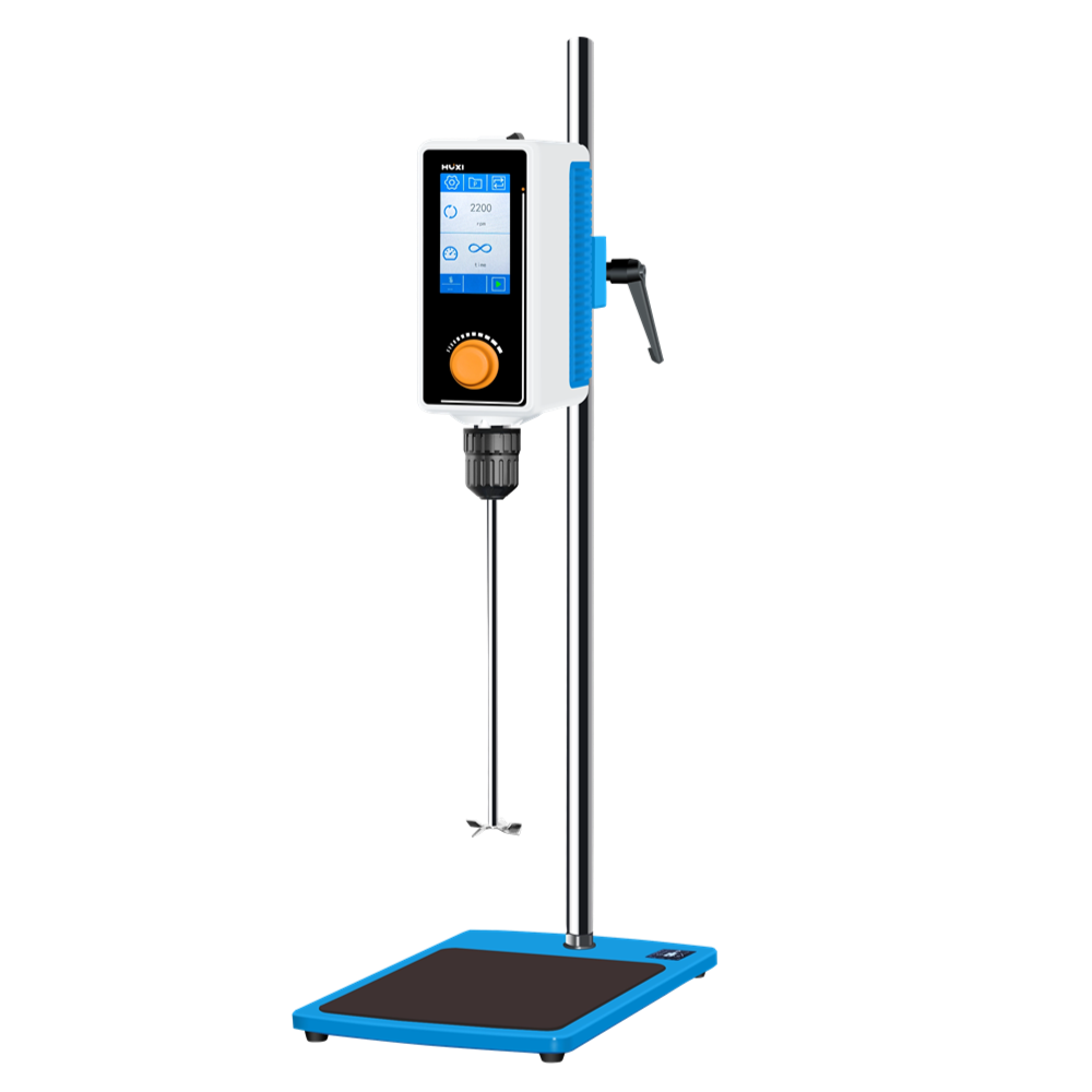
Direct-drive systems solve the decoupling problem entirely. An Overhead Stirrer physically connects the motor to the sample via a mechanical chuck and a rigid stirring shaft. There is no magnetic field to break. If the motor turns, the impeller turns. This physical connection guarantees continuous agitation even in heavy pastes, creams, or dense polymer melts.
To handle these dense materials, manufacturers incorporate heavy-duty gear reduction systems. A high torque stirrer trades maximum top-end RPM for raw rotational force. By passing the motor's output through a planetary or spur gear assembly, the mixer multiplies the torque delivered to the shaft. This mechanical advantage provides the necessary force to move highly viscous materials without stalling the motor or tripping thermal protection circuits. Direct-drive mechanics ensure that the energy you put into the system translates directly into fluid movement.
When evaluating specifications, you must differentiate between continuous operating torque and peak torque. Continuous torque indicates the rotational force the motor can sustain indefinitely without overheating. This serves as your baseline for long-duration mixing tasks. Peak torque represents short bursts of maximum force. The motor can only sustain peak torque for brief periods before thermal overload protection engages and shuts the system down.
Your success criteria rely on mapping these ratings to your specific chemical process. Establish your baseline torque requirements based on the maximum expected viscosity during a phase change. Do not base your equipment choice on the starting viscosity or the average viscosity. If an emulsion polymerization reaction spikes in viscosity at 80 percent conversion, your mixer must possess a continuous torque rating high enough to push through that phase without stalling.
Modern mixing requires absolute precision. Advanced microprocessor-controlled motors monitor the torque load on the shaft continuously. As the sample thickens and fluid resistance increases, the microprocessor detects a micro-drop in RPM. It instantly adjusts the electrical wattage sent to the motor coils to compensate for the drag. This feedback loop maintains a constant RPM under rapidly changing viscosity conditions.
This dynamic feedback directly impacts experimental reproducibility. If a specific chemical reaction requires exactly 300 RPM for optimal mass transfer, the motor must deliver exactly 300 RPM. Without a feedback loop, an analog motor will slow down as the fluid thickens. This alters the shear rate, changes the particle size distribution, and potentially ruins the entire batch. Microprocessor control ensures that your set parameters remain constant regardless of the fluid's physical state.
Viscosity and Flow Pattern Reference
Impeller Type | Flow Pattern | Optimal Viscosity Range | Relative Torque Demand |
|---|---|---|---|
Marine Propeller | Axial (Top to Bottom) | 1 to 500 mPa·s | Low |
Pitched Blade Turbine | Mixed (Axial and Radial) | 500 to 10,000 mPa·s | Moderate |
Flat Blade Turbine | Radial (Center to Walls) | 1,000 to 50,000 mPa·s | High |
Anchor / Paddle | Tangential (Scraping Walls) | 50,000+ mPa·s | Highest |
The physical design of the stirring element dictates how fluid moves within the vessel. You must match the impeller to the fluid rheology. If you select the wrong geometry, you will waste motor power and fail to achieve homogeneity.
Axial flow impellers, like standard marine propellers, push fluid down the shaft axis. The fluid hits the bottom of the vessel and sweeps up the sides. This geometry demands relatively low torque. It works perfectly for basic homogenization and suspending light solids in water or thin oils. The pitch of the blades determines the exact flow rate. A steeper pitch moves more fluid but increases the drag on the motor.
Radial flow impellers, such as flat-blade turbines, throw fluid outward against the vessel walls. This creates high shear zones near the blades. Radial flow demands moderate to high torque. We utilize this geometry for gas dispersion or breaking up agglomerates in medium-viscosity fluids. The flat blades act like walls pushing against the fluid, which requires significant rotational force from the drive unit.
Tangential flow impellers, like anchors and large paddles, sweep close to the vessel walls. They move the entire fluid mass as a single unit. These designs demand the highest torque. They are strictly required for highly viscous, non-Newtonian materials that resist flowing. If you use a small propeller in a heavy paste, it will simply bore a hole in the center of the material while the rest of the batch remains stationary. The anchor impeller prevents this by physically scraping the boundary layer off the vessel wall and folding it back into the center of the batch.
The ratio of the impeller diameter to the vessel diameter heavily impacts the torque load on the overhead stirrer. A small impeller spinning at high speeds generates localized high shear but leaves dead zones near the vessel walls. A large impeller spinning slowly moves the entire volume uniformly but creates massive drag.
This presents a clear mechanical trade-off. Larger impellers move more volume at lower speeds. This is excellent for shear-sensitive materials like cell cultures or delicate cosmetic emulsions. However, pushing a large surface area through a viscous fluid requires significantly higher baseline torque from the motor. You must match the impeller diameter not just to the vessel size, but to the maximum torque output of your direct-drive system.
Running a laboratory mixer at its maximum torque capacity for extended periods causes severe thermal overload. The internal copper coils overheat, the electrical insulation degrades, and the motor eventually burns out. Stalling occurs when fluid resistance exceeds the motor's maximum output. The shaft locks in place while electrical current continues to flow, creating a massive heat spike.
To mitigate these risks, specify equipment with built-in thermal protection circuits and automatic overload cut-offs. These safety features monitor the internal temperature of the motor housing. If the temperature exceeds safe operating limits, the circuit breaks the electrical connection and shuts down the motor before permanent damage occurs. Apply a strict safety margin during the purchasing phase. Always select a motor rated 20 to 30 percent above your maximum calculated torque demand. This ensures the motor operates comfortably within its continuous duty cycle, extending its operational lifespan and preventing unexpected downtime during critical experiments.
High torque combined with improper shaft alignment causes dangerous vibrations, known as shaft whipping. If the stirring shaft is too long and unsupported, the rotational force causes it to bend slightly. As RPM increases, this bend turns into a violent whip. Shaft whipping destroys internal bearings, ruins mechanical seals, and can easily shatter glass reactors.
Mitigate this risk by utilizing pass-through chucks. A pass-through chuck allows you to slide the shaft up through the motor housing. You can adjust the length precisely to the depth of your vessel. This minimizes the unsupported length of the shaft. Mount the mixer on heavy-duty stands with vibration-dampening bosses. This absorbs residual kinetic energy and maintains perfect vertical alignment.
Subjecting the motor to sudden torque shocks destroys gearboxes and snaps impeller shafts. Initiating mixing at high speeds in already-viscous samples forces the motor to overcome massive fluid inertia instantly. The fluid acts almost like a solid wall against the stationary impeller blades.
Implement gradual speed ramping protocols to prevent mechanical shock. Start the mixer at very low RPMs. Allow the impeller to carve a flow path and overcome initial fluid inertia safely. Once the fluid begins moving and momentum is established, gradually scale up to the target agitation rate. Many modern digital mixers feature programmable soft-start functions. These automate the ramping process, protecting both the sample and the mechanical drive train.
The type of motor driving the shaft dictates performance, maintenance requirements, and safety. Brushed motors utilize older technology to provide reliable rotational force. However, the internal carbon brushes wear down over time through physical friction. You must replace them periodically. More importantly, brushed motors generate internal sparks during operation. This makes them entirely unsuitable for environments containing volatile solvents or flammable vapors.
Brushless DC (BLDC) motors provide a superior technical solution. They utilize electronic commutation instead of physical brushes. This eliminates friction, resulting in zero maintenance and significantly quieter operation. BLDC motors deliver higher torque density. They provide more power in a smaller, lighter housing. They generate no sparks, ensuring safe operation in hazardous fume hoods.
Take the following immediate actions to upgrade your laboratory mixing protocols:
Calculate the peak dynamic viscosity of your most demanding formulation to establish a baseline torque requirement.
Audit your current impeller inventory and replace undersized propellers with tangential anchors for any fluids exceeding 10,000 mPa·s.
Install pass-through chucks on all direct-drive mixers to eliminate shaft whipping and protect glass reactors.
Program soft-start ramping profiles into your digital mixers to prevent gearbox damage from sudden inertial shocks.


